Visual can perform daylighting calculations and provide daylighting renderings in a single-instance mode; that is, for a particular place at a particular time. The basic calculation procedure is that same as that described for electric lighting; with the sky and sun considered as additional light sources.
To add the sky and sun as light sources, additional user data is required; used to find either the appropriate weather data from the Visual Weather Database, or to calibrate a CIE sky specified by the user. In addition, the diffuse reflectance of the surrounding ground plane must be specified, as well as glazing information.
Location is specified by Longitude and Latitude, specified in degrees. Positive and negative values of Latitude specify north and south the equator, respectively. Positive and negative values of Longitude specify east and west values from the Prime Meridian at Greenwich England. Longitude and Latitude are input by the user of come automatically from the Visual user interface Site Locator.
The default orientation of the Visual project site is that sky and sun North (geographic North) corresponds to +y in local Visual coordinates. A project orientation angle changes the relative angular position of the sky and sun with respect to the project. Positive values, in degrees, rotate the site clockwise when viewed from above. NB: this does NOT change the significance of the local Visual coordinates nor does it rotate the Visual drawing.
Date and time are local civil time. If in effect, daylight saving time should be indicated.
The Visual Weather Database is derived from all of the more than 2100 EnergyPlus data sets that cover most of the globe. For each location with a data set, only required radiometric or photometric data has been extracted from the hourly data. If only radiometric data is available at a particular site, photometric data is derived using a process devised by Perez. See: "Modeling Daylight Availability and Irradiance Components from Direct and Global Irradiance," R. Perez, P. Ineichen, R. Seals, J. Michalsky, and R. Stewart. Solar Energy. Vo. 44, No.5. pp 271-289.
In all cases, the primary photometric data that is extracted or generated for every available site are hourly values of direct solar illuminance and total horizontal sky illuminance for each data of the year. Data in the EnergyPlus weather file for a particular site are usually constructed from several years of measurements, aggregated together to establish a Typical Meteorological Year for that site.
The fundamental luminous properties of sun and sky are the direct solar illuminance and the total horizontal illuminance produced by the sky. These are either: 1) derived from weather data, or 2) calculated using IES standard sun and sky parameters. See: IES Lighting Handbook, Chapter 7, Section 7.9 Formulary.
The sun is modeled as a luminous disc, ½-degree in diameter. Its luminous power is expressed as the direct, unoccluded illuminance produced on a surface with its normal pointed to the sun. Solar position is determined from the location and local time. See: IES Lighting Handbook, Chapter 7, Section 7.1.5 Solar Position.
The sky is modeled as a luminous dome, with a relative luminance distribution determined according to ISO/CIE Standard 15469, 2nd edition. The parameters that determine the distribution are either derived from the appropriate weather data or come directly from the standard set of parameters if the user specifies a specific CIE sky. See: "All-weather Model for Sky Luminance Distribution – Preliminary Configuration and Validation," R. Perez, R. Seals, and J. Michalsky, Solar Energy, Vol 50, No 3, pp 235-245.
NB: Standard weather data aggregates the illuminance from a circum-solar 5-degree circular patch of the sky with the direct illuminance from the sun. Therefore, the sky is modeled with a 5-degree hole centered on the sun.
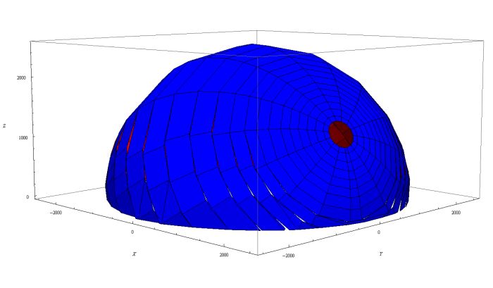
The Visual calculation engine establishes a distance, based on the maximum extents of the project that defines the distance to the sun and the radius of the sky dome. The distance is such that that parallax error over the extent of the project to any point on the sky dome is less than ½-degree. The sky is discretized into planar rectangles, accounting for luminance gradient. Using the luminance distribution, element size, and sky dome radius, each discretized sky element is assigned a luminous power defined by the direct normal illuminance it produces at the center of the Visual project.

Sky dome approximated with planar rectangles, sized and distributed according to the luminance distribution of the sky. Notice the 5-degree hole left for the sun and its circum-solar component.
A ground plane is automatically established around the project and horizontally positioned at Visual local z=0.0. Its reflectance is user-specified. The plane is automatically discretized into elements that are truncated wedges surrounding the project.
Skylight and sunlight illuminate any outward-facing user-specified surfaces and the elements of the ground plane. Occlusion by any other surfaces in taken into account. Skylight and sunlight illuminate any surface of an otherwise inward-facing or closed set of surfaces if admitted by an aperture, window or skylight. An aperture is a user-specified opening in an otherwise opaque surface. A window is an aperture into which a user has specified an image-preserving transmittance less than 100%. A skylight is an aperture into which a user has specified either an image-preserving or a diffuse transmittance.
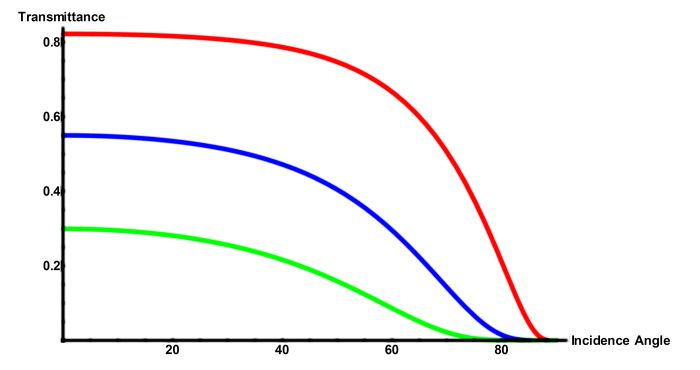
The image-preserving transmittance specified by the user is assumed to be the perpendicular or normal transmittance. The Visual calculation engine accounts for the reduction from this value due to increased incident angles. The Fresnel Laws of Reflectance and Transmission are used to determine this transmittance value. This calculation is done automatically whenever flux is passing through a surface with an image-preserving transmittance and uses the normal transmittance, the incidence angle, the number of glazing layers, and the assumed index of refraction for glass of 1.5.

Example of transmittance as a function of incidence angle for single, double, and triple glazing.