 |
 |
|
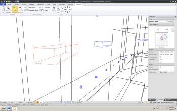
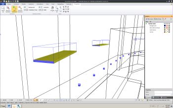
| Wireframe view showing luminaire template | Wireframe view showing luminous volume | |
|
|
||
 |
 |
|
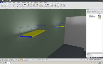
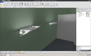
| Rendered view showing luminous volume | Rendered view showing luminaire model |
All photometric information about a luminaire is assumed to be contained in an IES/ANSI LM-63-02 formatted file. The luminous extent is specified with three local luminous dimensions: x, y, z. As defined in the standard, various combinations of zero, positive, and negative values are used to indicate various luminous forms. Regardless of the form indicated in the photometric data file, ALL luminaires are assumed to be luminous parallelepiped (rectangular boxes). The dimensions of the approximating luminous box are determined to best fit the values and shape provided in the photometric data file. These boxes are considered at luminous volumes in the Visual calculation engine.
The luminous intensity distribution specified in the file is used to determine which of the six faces of the luminous volume are photometrically active. The "Luminous Volume" button in the "Luminaire" tab of the Visual user interface toggles these faces on and off. Faces colored yellow are those the calculation engine has made photometrically active, those in blue are inactive.
The total luminous radiant power of the luminaire (luminous flux) is distributed among the active surfaces, with the total being equal to that of the entire luminaire. Individual faces have individual distributions appropriate for their orientation and size. The sum of these distributions equals that of the entire luminaire.
Examples are the following. A lensed troffer has only the local bottom surface photometrically active. A surface-mounted wraparound with have three faces active: the bottom and the two long sides. A sharp-cutoff highbay will have 5 surfaces photometrically active: the bottom and four sides.
|
No form of commonly used photometric data file contains information about luminaire appearance or luminaire surface/opening luminance distribution. Therefore, the Visual calculation engine assumes that the luminous power of any active face of a luminous volume is homogeneous; that is, on any luminous face, the per unit luminous radiant power and distribution are everywhere the same. However, these values can and do differ from active face to active face.
Advanced techniques are used to calculate either the illuminance at point or the incident flux on a surface produced by any one face of a luminaire luminous volume. These rely on the assumed homogeneity of each active surface, account for the area of the active face, and eliminate the need to discretize the face into assumed point sources. Additionally, they are computationally faster than the point discretization technique.
The Visual calculation engine uses a procedure to calculate the illuminance at a point from a face of a luminaire luminous volume that was first discovered in 1994. A numerical contour integration is performed around the edges of the face. Details can be found in the technical paper: "Non-Diffuse Radiative Transfer 1: Area Sources and Point Receivers," D.L. DiLaura and J. Quinlan, Journal of the Illuminating Engineering Society, Summer 1995, Vol. 24, No. 2, pp. 102-113.
The Visual calculation engine uses a procedure to calculate the flux onto another surface from a face of a luminaire luminous volume that was first discovered in 1996. A numerical double contour integration is performed around the edges of the face and the receiving surface. Details can be found in the technical paper: "Non-Diffuse Radiative Transfer 4: General Procedure for Planar Area Sources and Area Receivers," D.L. DiLaura and S.R. Santoro, Journal of the Illuminating Engineering Society, Winter 1997, Vol. 26, No. 1, pp. 188-200.
The illuminance calculated at any user-specified point in a calculation zone can be of several types: Directional, TV, Maximum Spill, LEEDS Trespass, Spherical, and Constrained Maximum. These can be obtained from two types of basic illuminance calculations: with and without one or more illuminance normals. In the former, incident flux is weighted with the cosine of the angle between the incidence direction and illuminance normals. In the latter, the incident flux is not weighted. Spherical Illuminance, for example, uses no illuminance normal, Directional Illuminance uses one illuminance normal at each point oriented in a fixed user-specified direction, TV Illuminance uses an illuminance normal that changes orientation from point to point, and Maximum Sill use 6 illuminance normals, one in each of the cardinal directions.
Illuminance is determined in a two-step process. An illuminance is calculated using an appropriate method and assuming the light source has an unobstructed view of the illuminated point. Then, if potential occluding objects are detected (surfaces, other luminaires) an occlusion factor is calculated, ranging from 0.0 to 1.0, from full occlusion to no occlusion, and is used as a multiplier for the illuminance, reducing it if appropriate.
The occlusion factor is determined by ray-casting. An angularly uniform spray of rays is established between the illuminated point and the surface of the source. The angular separation is ½ degree. The number of rays intercepted by luminaires or surfaces is determined. If a ray is intercepted by an opaque or diffusely transmissive surface, the surviving ray count is reduced by one. If the only surface(s) involved have an image-preserving transmittance, the ray count is reduced by the transmittance. The occlusion factor is the ratio of the remaining ray count to the total number of rays.
Direct illuminance is that produced by a luminaire and is calculated using the numerical contour integration method described above, assuming the light source has an unobstructed view of the illuminated point. If possible occluding surfaces are present, an occlusion factor is determined.
Interreflected illuminance is produced by: 1) the light reflecting from surfaces that are illuminated by sources or other reflecting surfaces and, 2) light transmitted through a diffusely transmissive surface illuminated from the opposite side. In both cases, the source is assumed to be perfectly diffuse (either because it is diffusely reflective or diffusely transmissive) and has a uniform exitance.
The illuminance at a point with an illuminance normal is calculated from the equation:

Where Ei is the illuminance at the point due to the ith diffusely luminous surface, Mi is the uniform surface exitance, Ci is the unoccluded geometric configuration factor from the point to the luminous surface, and ai is the occlusion factor. The total interreflected illuminance at the point is the summation of that produced by all the diffuse surfaces:
![E=Sum[M_i x C_i x α_i]](../../images/The_Calc_Engine/Equation2.png)
The configuration factors are purely geometric quantities and the standard equation is used for a point and a planar polygon. Details can be found in the IES Lighting Handbook, Chapter 10.
The illuminance at a point with no illuminance normal is calculated from the equation:

In this case, wi is the solid angle subtended at the point by the luminous surface. The total illuminance is the summation over all the diffuse surfaces.
Interreflected illuminance calculations require the exitance of diffusely reflecting and transmitting surfaces. The exitance of these surfaces originates from light incident directly from sources (referred to as initial light or initial flux) which is increased by the interreflection of light between surfaces. This is known as Radiative Transfer Analysis and is also referred to as Radiosity. The procedure is described, in outline in the IES Lighting Handbook, Chapter 10.
The computational procedure has two essential characteristics: otherwise continuous surfaces are broken up or discretized into small subsurfaces, and each subsurface is characterized by a single exitance produced by initial and interreflected light. How accurately the collection of uniform, individual exitances represent the actual exitance distribution across a large surface depends on the shape of the surface and its illumination conditions. The Visual calculation engine discretizes user-specified surfaces using several criteria and produces subsurfaces of sufficient number to balance necessary accuracy with computational time. This discretization process and the other aspects of the radiative transfer analysis used in the Visual calculation engine are described in the following sections.