 |
 |
|
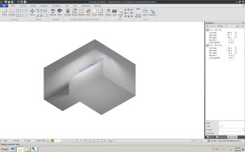
Rendering |
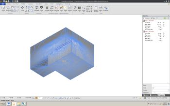
Rendering showing component triangles |
The Visual calculation engine can produce most of the data required to display a photometrically accurate rendering of a project. The assumptions underlying the calculations are the same as those for the general radiative analysis of the project; the most important are diffuse reflectance and spectral flatness. Since all surfaces are diffuse, the calculations required for a rendering can be performed once and provide all the data required for any view of the project desired by the user. Thus, changing views or navigating through the project does not require recalculation, only a change of the subset of data which is displayed.
The basic procedure used in the Visual calculation engine to generate renderings has three steps: 1) generate arrays of triangles that cover user-specified surfaces and have exitances that are photometrically accurate, 2) display these triangles in an appropriate geometric and screen-luminance manner, and 3) refine the rendering with multiple calculation passes to more accurately model surface exitance distributions.
The determination of the necessary triangles begins with an array of illuminances calculated on a user-specified surface. At each point in this array, the possibly-occluded direct and interreflected illuminance is calculated. This is a double-pass process: after the illuminances at each grid point are determined, each 2-point x 2-point subsection of the grid is examined for high gradients. If a high gradient is present, that subsection is arrayed with additional, more tightly spaced points. Illuminances are calculated at each of the points in each such subgrid during a second pass. This brings out necessary detail in the exitance distribution on the surface while minimizing calculation time.
Based on the project type, and the range and gradients of illuminance found in the array, points defining up to 256 iso-illuminance contour lines are determined. The points along a contour vary in spacing; small spacing where the line is highly curved, and large where the line is straight.
To provide for necessary detail, additional illuminances are calculated along the lines that form the boundary of the surface and along lines defined by the intersection of the surface with other surfaces in the project. These additional illuminances help define sharp shadows and accurately portray touching surfaces.
A collection of triangles is built from the points along the contour lines and the added illuminance points. Constrained Delaunay triangularization is used. The constraints are the edges formed by the sections of contour line, and the sections connecting the points along the additional lines of illuminance. The outline of resulting triangles can be toggled on and off in a rendering with the 7-key.
|
As each surface to be rendering in the project is processed, a record is kept of the number and extent of high gradients. If adaptively determined re-rendering criteria are met, the surface is flagged for an additional rendering calculation pass.
After all surfaces have been processed, the Visual user interface takes the triangle data provided by the calculation engine and generates the rendering display. Meanwhile, the calculation engine processes all surfaces that have been flagged for additional work. In this addition pass, the density of all illuminance points on the surface is incremented and the calculation-triangularization process outlined above is repeated. Not all surfaces may require additional calculation.
When the engine completes processing these flagged surfaces, the Visual user interface updates the data it has on all surfaces, replacing previous data for a surface with any that was generated during the addition rendering computation.
This entire process is repeated up to four times. Each time the rendering calculations are performed on a denser grid of points. It is usually the case that the list of surfaces that are recalculated and updated gets smaller with each pass.
Surfaces handled in the Visual calculation engine are planar. In many cases any array of these approximates the surface of a dome, or a column, or a curved wall. To make renderings of such surfaces more realistic, special processing can be invoked, at the discretion of the user, to more faithfully render them by eliminating the abrupt change in exitance that is otherwise present on either side of an edge shared by surfaces that meet at even a slight angle.
If a user-specified surface meets another at an angle less than 20-degrees then the illuminance normals used in the surface illuminance calculation are modified. All edges of a surface are examined to see if the angle to the adjoining surface is less than 20-degrees. If so, the normal at the vertices involved are changed from that of the original planar surface (which is the default case) to an average formed with the normals of the original surface and those adjoining it at the required small angle. These new, interpolated normals can spread outward, defining a convex surface, or bend inward, defining a concave surface.
The position and orientation of the vertex normals are used to define a new, temporary convex or concave surface that passed through the original surface vertices. This temporary surface is used to define new calculation points and illuminance normals than produce illuminances for a local, curved surface. These points and illuminances are used in the manner described above to generate rendering triangles.
|