Rooms, Structures, and Walls (or other more complex obstructions like modular furniture shown at right) can all have a dramatic impact on lighting system performance and it is frequently important to model these features to then take them into account in the calculation.
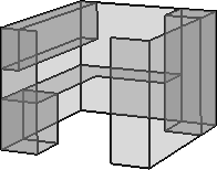
In Visual, such items are comprised of one or more Solid Objects in the form of Rectangles, Polygons, or Circles.
Solids can be constructed in a pre-grouped fashion as Rooms and Structures.

Visual creates Solid Objects with a coplanar front and back having the same properties. There is no need to create extra surfaces to have a correct model, as is the case in some other lighting software. A common wall can be created between two rooms without impacting the average noticeably in most cases if it is convenient. For example, a 60x40 room versus a 61x41 room will have 1% difference in average illuminance with the same lighting system, which is inside the 2% standard photometric test error. Imported CAD files almost always contain both sides of a given wall, and when an enclosed Room is created, Visual's algorithms calculate succinctly so the seeming duplication is not a detriment. See Rooms and Structures for more information.
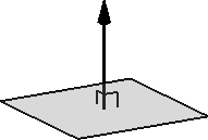
Solids are created with a Surface Normal to discern the front face from the back face. This is stored in the object Properties and accessed with the Properties command. The Surface Normal is a unit vector. (0,0,1) indicates the positive-z direction. (0,1,0) indicates the positive-y direction. (1,0,0) indicates the positive-x direction.
The Surface Normal is important in that Visual uses that information (which side is the front side) when (for example) a Calculation Zone is placed on a Solid. See Placing Calculation Zones on Existing Solid Objects
The Surface Normal can be "Flipped" by modifying object Properties. See Solid Properties.
Solid Circles, Rectangles, and Polygons can be converted to Background objects if necessary. See Converting Object Types. (Note that the resulting Background objects will have a Line Width of 1.)

It is important to select Color and Reflectance to align with the properties of the materials in the actual project. For example, 80% Reflectance is valid for a ceiling composed of higher end acoustic tile, but is certainly not appropriate for raw materials used in most "open to deck" scenarios or sprayed-on insulation, especially when an indirect luminaire is used. The default is 50% Reflectance for all Solids.

The choice of a Color is only necessary if Color Rendering is a desired output from Visual. Grayscale choices yield the same numeric results as "colored" choices, assuming the Reflectance value is the same.
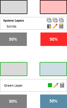
The Color and Reflectance chosen for Solids is independent of the Layer Color. The Layer Color is used to provide user feedback in the Design Environment and the Color and Reflectance is used for calculation.
On the right, the objects with a black border have different Color (and therefore Reflectance ) on the Solids System Layer (Color is ByLayer) and those with a green border are on a separate Layer, also with different Color (and Reflectance ). In Shaded Display Mode shown at the bottom, borders (drawn in the Layer Color) are not shown. The gray, red, and blue all yield the same calculational result because they are all 50% Reflectance .
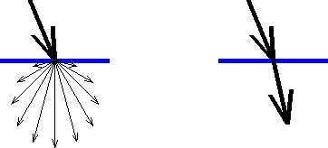
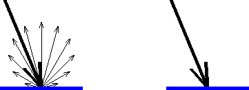
Solid Objects can be modeled to simply block the direct travel of light or reflect light diffusely. See Editing Object Properties for more information.
Solids can be modified to transmit light diffusely or transparently. See Editing Object Properties for more information.
