The Axis button can be found on the Construct tab of the Ribbonbar.

To create an Axis, select the Base Point with the mouse, keyboard, or Object Snap.

Movement of the mouse in the command shows the implied Axis that will be drawn in the Active Plane.

Axis Increment indicates how far apart Axis tick marks and labels are created.
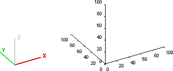
At right, the Axis command has been used to draw an Axis from the (0,0,0) origin in each of the x, y, and z cardinal directions.

Select the endpoint of the Axis line with the mouse, keyboard, or Object Snap. Visual automatically ends the command and draws the Axis.

The Global Axis option restricts the Visual Axis to being parallel with one of the Cartesian axes. Axis labels are coincident with the X, Y, or Z-dimension related to that spot on the Axis.

The Relative Axis option allows for an Axis to be placed such that labels are based on zero being the Base Point of the Axis as specified and labelling is independent of global (X.Y.Z) coordinates. The Axis can be applied at any angle in the Active Plane.
At right, the global coordinates are indicated for each Relative Axis, which then aligns with the Global Axis example above.

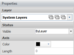
After creation, Layer, Color, and visibility Properties can be modified.
Label, line, and tick mark use the same Color for each Axis.
