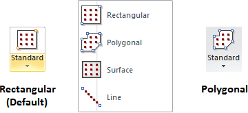
The buttons for the various types of Calculation Zones can be found in the Calculations panel on the Home tab or the Calculation Zone panel on the Calculations tab of the Ribbonbar.

The Home tab buttons are dual function; the upper portion executes the command, the lower portion initiates a drop-down menu.
Once a selection has been made other than the default, the upper button portion will change to execute that command with the next press and the graphic is changed accordingly. Selecting one of the other commands from the drop-down menu will revert the button to that mode.

Rectangular and Polygonal Calculation Zones share a similar interface in the Properties tab of the Ribbonbar that is shown upon command execution.
See Calculation Zone Parameters for information on specific parameters.

Note that the basic process of creating Calculation Zones is identical to that of creating Background or Solid Rectangles and Polygons except that additional information must be entered on the Properties tab to space and format the points.
To construct a Rectangle Calculation Zone, specify the coordinates of the first vertex using the mouse, keyboard, or Object Snap. In the command, moving the mouse causes Visual to draw the implied Rectangle showing what will be created when the command is completed. To end the command, right-click the mouse or press Enter. Various parameters can be specified in the Properties tab as discussed below.

To construct a Polygon Calculation Zone, specify the coordinates of the vertices using the mouse, keyboard, or Object Snap. In the command, moving the mouse causes Visual to draw two types of implied lines: the small-dash line connects the first vertex and the last vertex specified and the large-dash line connects the cursor to the last vertex specified. To end the command, right-click the mouse or press Enter. Various parameters can be specified in the Properties tab as discussed below.

When changes have been made to the lighting model that require a re-calculation, Visual will indicate that Calculation Zone values may no longer be valid by bracketing point values.
