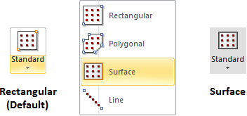
The buttons for the various types of Calculation Zones can be found in the Calculations panel on the Home tab or the Calculation Zone panel on the Calculations tab of the Ribbonbar.

The Home tab buttons are dual function; the upper portion executes the command, the lower portion initiates a drop-down menu.
Once a selection has been made other than the default, the upper button portion will change to execute that command with the next press and the graphic is changed accordingly. Selecting one of the other commands from the drop-down menu will revert the button to that mode.

Surface Calculation Zones have the identical interface in the Properties tab of the Ribbonbar that is found when placing Rectangle and Polygon Calculation Zones.
See Calculation Zone Parameters for information on specific parameters.

To place a Calculation Zone on a Surface, select the desired Surface to use as the basis by left-clicking, specify parameters as necessary in the Properties tab, and press Enter or right-click to end the command. The selection of a Surface provides the bounding polygonal (or rectangular) shape just as if that shape had been provided while executing the commands as described in Rectangular and Polygonal Calculation Zones.
Note that the Height is applied from the Surface itself not the Cartesian coordinate system.

The normal of the Calculation Zone (and therefore the virtual light meter) will be pointed to the interior when placed on Room Surfaces and pointed to the exterior when placed on Structure Surfaces.
For the same reasons, Calculation Zones placed on Room Surfaces will be offset to the interior of the Room. Calculation Zones placed on Structure Surfaces will be offset to the exterior of the Structure. This of course assumes a non-zero Height is specified.
