To activate the Properties command, click the Properties button on the Home tab of the Ribbon Bar or in the Sidebar, or press the "P" hotkey. When a Luminaire object is selected, Visual displays the properties for that object in the Sidebar.

For Luminaire objects, Visual displays the following panels:
The Layer panel indicating on which layer the object resides. The layer may be changed by clicking the drop-down menu arrow on the right. "System Layers" is the default and is in fact a Layer Group, which indicates the object is on the Background layer of the System Layers group. See Layers for more information.

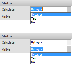
The Status panel contains Calculate and Visible menus that allow control of individual objects. Selecting "Yes" means the object(s) will be used in calculations or will be visible. Selecting "No" means the object(s) will not be used in calculations and will not be visible. "ByLayer" indicates that control of object visibility and use in calculations is controlled by selections made in the Layer Manager for Editability and Calculation State.
Once an object has been made not visible with this dialog, the only way to get access to the object is through the Design Manager where the object can be selected and made visible again, for example.

The Luminaire Type panel contains:
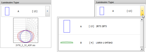
Luminaire Selector, which is a reduced drop-down version of the Luminaire Schedule. showing Luminaire Label and Count. The drop-down menu shows the truncated schedule Label, Count, and Catalog Number.
Candela Distribution showing the shape of the luminaire output with the name of the photometric file below the polar plot.

The Position panel contains:
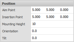
Aim Point is an editable X,Y,Z triplet indicating where the Luminaire is aimed. Unless the Luminaire was inserted with Place & Aim, Visual assumes the aim point to be in the Z=0 plane.
Insertion Point is an editable X,Y,Z triplet indicating where the Luminaire is placed. Unless the Luminaire was inserted with Place & Aim, Visual assumes the placement to be in the Z=0 plane.
Mounting Height of a Luminaire is set when a Luminaire is placed and can be modified to any value to suit the design intent.
Orientation indicates the rotation of the Luminaire with respect to the 0° X-axis. See 3.2 The Luminaire Editor for more information.
Tilt is the angle of inclination with 0° being straight down, 90° being at the horizon, and 180° being straight up.

The Display panel contains:
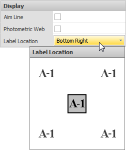
Aim Line is a checkbox that turns on or off the display of the line from the Luminaire to the Aim Point. This can be very useful to illustrate where luminaires are aimed for certain project types like facade lighting.
Photometric Web is a check box that turns on or off the display of a pseudo-scaled 3-D mesh illustrating the shape of the candela distribution for the selected Luminaire.
Label Location is a drop-down menu with 5 location choices to avoid possible overlap of Labels when displayed in certain situations.

Multiple objects can be selected and modified. Properties that do not have the same value will have an ellipsis entry indicating multiple values. The ellipsis can be clicked and parameters modified as normal, thus setting that value to all objects; for example, color or layer.

After Properties have been suitably modified, click the right mouse button to end the command and apply parameter modifications.
