Calculation Zones are often placed at some level above grade (workplane height). While this can certainly be accomplished by choosing the correct coordinates when entering the Calculation Zone parameters, the Height field provides an alternative method. When a Height value is entered, the points in a Calculation Zone will be displaced perpendicularly from the working plane (plane of the crosshairs) in the direction nearest the point of view. For horizontal Calculation Zones this will typically be in the direction of the positive Z-axis as would be commonly desired.

Rectangular and Polygonal Calculation Zones result in an array of points and thus, spacing values must be entered for each dimension of the array. In the case of a Line, calculation points are spaced with the specified increment along the path of the Line.

Color can be selected from the Properties tab in the Ribbonbar that will automatically be shown. This selection modifies the points and the associated numerical text. See Using the Color Dialog for information on selecting Color.

The Point Style for a Calculation Zone can be chosen at creation. Clicking the button initiates the drop-down graphical menu that illustrates the available Point Styles at right.

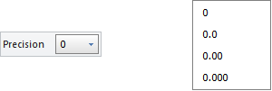
Precision specifies how many decimal places should be shown for the Calculation Zone. Clicking the button initiates the drop-down menu to allow for the selection of 0 to 3 digits. It is not possible to display more than 3 digits because it is beyond the accuracy of photometric testing in most cases.

The Offset Points checkbox tells Visual to either center the grid of calculation points (checked) or to start spacing in the lower left corner (the corner with the smallest x, y, and/or z coordinates if creation occurs outside the x-y plane), which is likely to leave space between the last points and the edges of the boundary.
