To activate the Properties command, click the Properties button on the Home tab of the Ribbon Bar or in the Sidebar, or press the "P" hotkey. When a Calculation Zone object is selected, Visual displays the properties for that object in the Sidebar.

For Calculation Zone objects, Visual displays:
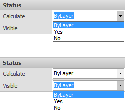
The Status panel contains Calculate and Visible menus that allow control of individual objects. Selecting "Yes" means the object(s) will be used in calculations or will be visible. Selecting "No" means the object(s) will not be used in calculations and will not be visible. "ByLayer" indicates that control of object visibility and use in calculations is controlled by selections made in the Layer Manager for Editability and Calculation State.
Once an object has been made not visible with this dialog, the only way to get access to the object is through the Design Manager where the object can be selected and made visible again, for example.

The Layer panel indicating on which layer the object resides. The layer may be changed by clicking the drop-down menu arrow on the right. "System Layers" is the default and is in fact a Layer Group, which indicates the object is on the Background layer of the System Layers group. See Layers for more information.

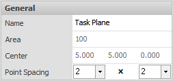
The General panel contains:
Name is the user-specified name or the Visual default.
Area is shown in square feet or square meters inside the polygonal solid boundary.
Center is the X,Y,Z triplet coordinates for the geometric center of the Polygon.
Point Spacing shows the spacing of points in X and Y axes respectively and allows modification with drop-down menus and the associated text boxes.

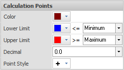
The Calculation Points panel contains:
Color shows the currently selected Color and allows for modification with the Color dialog.
Lower Limit defines the Color of the value highlight and allows specification of the type of highlight. Minimum indicates only the lowest value is highlighted. Choosing a value from the drop-down or typing a value will highlight values less than or equal to that value.
Upper Limit defines the Color of the value highlight and allows specification of the type of highlight. Maximum indicates only the highest value is highlighted. Choosing a value from the drop-down or typing a value will highlight values greater than or equal to that value.
Decimal indicates how many digits are displayed.
Point Style illustrates the selected symbol used to indicate each calculation point and allows modification to one of 5 choices.

The Display panel contains:
Calculation Points is a checkbox indicating if points are shown or not.
Contours is a checkbox indicating if the iso-illuminance contours are displayed or not on a per-zone basis. Once Contours are turned on in the Calculations tab of the Ribbonbar, this allows for individual zone contours to be displayed or not.
Shaded is a checkbox indicating if pseudo-color shading is turned on or off.

The Calculation panel contains:
Type is a drop-down menu for selection of one of the 7 ways in which Visual handles meter orientation.
Measurement is a drop-down menu allowing selection of one of 4 calculation units/methods.
Reflectance is a text box for specification of the necessary parameter for non-Illuminance calculations.
See Calculation for more information.

The Calculation Parameters panel contains:
Normal is the direction the perpendicular to the surface points in a unit vector. i.e. (0,0,1) would indicate the plane of the Calculation Zone is in the positive Z direction.
Orientation indicates the rotation of the "meter" associated to each point of the Calculation Zone with respect to the 0° X-axis.
Tilt is the angle of inclination of the "meter" associated to the Calculation Zone with 0° being straight up, 90° being at the horizon, and 180° being straight down.

When modifying a Calculation Zone created with the TV option, Visual displays the location of the camera for modification. See Calculation Types

The Flip button rotates the surface Normal 180°. When using the Calculation Zone Surface command, Visual places the grid on the "front" face of the solid. Depending on the order in which the vertices were chosen, the result of this command may not place the grid on the desired side. Therefore, the Flip button would make the other side of the solid the "front" and Visual would place the grid on the opposite side.

Multiple objects can be selected and modified. Properties that do not have the same value will have an ellipsis entry indicating multiple values. The ellipsis can be clicked and parameters modified as normal, thus setting that value to all objects; for example, color or layer.

After Properties have been suitably modified, click the right mouse button to end the command and apply parameter modifications.
