The Luminaire panel sets defaults for Luminaire placement in the Design Environment.
Display Photometric Web will show a scaled 3D mesh of the candlepower curve attached to the Symbol.
Mounting Height is the default used when placing a Luminaire, but the Mounting Height can be modified at placement.
Orientation is the default used when placing a Luminaire, but the Orientation Angle can be modified at placement.

Luminaire Aiming panel settings are useful in floodlighting projects.
The first option will hold the Aiming Point coordinates constant when Moving a luminaire.
The second option moves the Luminaire Label from near the Luminaire to near the Aiming Point.
Enable Aim To Surface allows Visual to provide input and as to which surface a Luminaire is aimed. See Place and Aim Luminaires for more information.

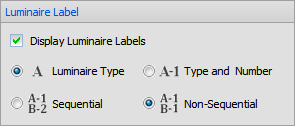
The Luminaire Label panel controls default display of Labels. Checking the checkbox tells Visual to display Labels by default and activates the rest of the panel. Using the top radio buttons, the choice can be made to display just the type or the type and the number. If "Type and Number" is chosen, the lower radio buttons control the default method used to assign numbers.
See Luminaire Display Options for information on making modifications to change the defaults and more information on the topic.

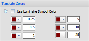
Default Template Colors and magnitude can be set (not to be confused with Contours) to apply to new Luminaire Types.
Selecting Use Luminaire Symbol Color will assign all Template lines to the Color of the Symbol and override any other selections.

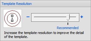
Template Resolution can be changed to include a greater or lesser number of segments in the polyline components. The recommended value should be acceptable for a majority of situations.
In some cases, photometry is overly sparse and the user may want greater smoothing between data points. This may not correlate to the reality of photometric output so changes should be made with direct knowledge it is necessary and valid.
Increasing above the recommended value may cause graphic display lag depending on computer hardware configuration.

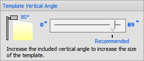
Visual includes only a portion of photometric output to speed Template display. Changing the Template Vertical Angle will include more or less photometric information. The graphic at the left of the panel displays the actual angle of inclusion and a dynamic graphic describing the inclusion angle visually. (The recommended angle is 80°.)
In a vast majority of cases, this setting should not need to be changed. If output is low or Template lines have very small illuminance values, truncation may be seen in the Template and adjusting the inclusion angle higher would be valid.
Increasing the angle may cause a noticeable lag in certain computer performance aspects depending on computer hardware configuration.

Settings made in subgroups indicated with a "*" and shown in dark red will not change existing objects.
