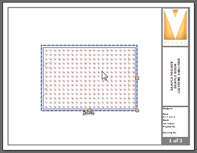
To modify a Drawing, left-click the Drawing to be modified. Visual will highlight the Drawing with a dashed border and provide grips.

Drawings are by default given a name that is placed below the Drawing on the Page. This name can be moved by left-clicking it separately, and moving it with a left-click-drag operation as should be expected. The text that appears (other than the scale text) can be modified by using the advanced Properties tab in the Sidebar; the Text field in the Content sub-section is where alternate text can be input. The name can be deleted by highlighting it individually and clicking the Delete button in the Ribbonbar or pressing the Del key.

The Properties tab is displayed in the Print Editor Ribbonbar. The Drawing panel contains elements to modify the selected Drawing.

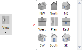
The View button initiates the same drop-down graphical menu used at initial creation, and thus changes the view direction. Simply left-click the desired view direction and the change is applied.

The Scale checkbox tells Visual to apply a particular Scale to the Drawing. The default for orthogonal views is to use a Scale. The default for isometric views is to not use a Scale. Make selections from the combo boxes, type custom values as desired, or use the grips as described below.
See http://en.wikipedia.org/wiki/Architect%27s_scale and http://en.wikipedia.org/wiki/Engineer%27s_scale for information on scaling drawings.

Contours is a toggle button that turns on or off the display of Contour Lines. This does not override the setting in the Design Environment; i.e. to display Contour Lines in Print Editor, they must be turned on in the Design Environment. The feature is on when the button is gold. See Setting and Displaying Contours for more information.

Labels is a toggle button that turns on or off the display of Luminaire Labels. This does not override the setting in the Design Environment; i.e. to display Luminaire Labels in Print Editor, they must be turned on in the Design Environment. The feature is on when the button is gold. See Luminaire Display Options for more information.

Masks is a toggle button that turns on or off the display of Calculation Zone Mask boundaries. This overrides the Design Environment setting if necessary. See Masking Calculation Zones for more information.

Templates is a toggle button that turns on or off the display of Luminaire Templates. This does not override the setting in the Design Environment; i.e. to display Templates in Print Editor, they must be defined and turned on in the Luminaire Schedule and Design Environment. The feature is on when the button is gold. See Luminaire Display Options and Luminaire Templates for more information.

Symbol is a toggle button that turns on or off the solid fill shading of Luminaire Symbols. This can be useful in site lighting projects where the size of the project dwarfs the luminaires and they can be hard to see. Note that turning this feature on likely blocks the view of information "below" the luminaires; i.e. Calculation Zone point illuminances.

Web is a toggle button that turns on or off the display of Photometric Webs for all Luminaires. This overrides the display setting in the Design Environment and will turn on Photometric Webs even if they are turned off there. See Luminaire Display Options for information.

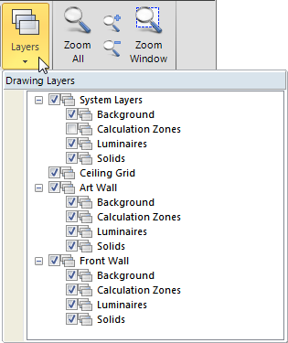
Clicking the Layers button initiates the Drawing Layer Dialog that allows for each Layer defined in the Design Environment to be turned on or off by placing a check in the related box (to turn a Layer on). This can be used to override Visibility settings in the Layer Manager.
Layers made Invisible in the Design Environment will be unchecked as is shown at right for the Calculation Zones System Layer.

When the mouse cursor is over a grip (yellow boxes on the perimeter of an object), a double-arrow will be displayed. Left-click any grip, hold, and move the mouse to change the size of the object. When the left-click is being held, the mouse cursor will be a pointing finger. Release the mouse to apply the change.

As the mouse is moved when scaling, Visual displays different scales at the top of a Drawing to aid in sizing to fit the Page. The blue size tag that will be used as the scale when the mouse is released will have bold white text as in "10' " at right.
