The buttons for the various types of Calculation Zones can be found in the Calculations panel on the Home tab or the Power Density panel on the Calculations tab of the Ribbonbar.

The Home tab buttons are dual function; the upper portion executes the command, the lower portion initiates a drop-down menu.
Once a selection has been made other than the default, the upper button portion will change to execute that command with the next press and the graphic is changed accordingly. Selecting one of the other commands from the drop-down menu will revert the button to that mode.

Rectangular and Polygonal Power Zones share a similar interface in the Properties tab of the Ribbonbar that is shown upon command execution.
Name allows Power Zones to be individually identified for later use and presentation clarity.
Color can be selected to modify the highlight given to the zone in the Design Environment. See Using the Color Dialog for information on selecting Color.
Precision specifies how many decimal places should be shown for the Calculation Zone. Clicking the button initiates the drop-down menu to allow for the selection of 0 to 3 digits.

To create a Rectangular Power Zone, select the two necessary corners that define the rectangle with the mouse, keyboard entry, or Object Snap. Right-click the mouse or press Enter to advance the command to the next step. Select the luminaires to be associated to the Power Zone, see Selecting Objects. Right-click the mouse or press Enter to end the command.

To create a Rectangular Power Zone, select the vertices necessary to define the polygon with the mouse, keyboard entry, or Object Snap. Right-click the mouse or press Enter to advance the command to the next step. Select the luminaires to be associated to the Power Zone. Right-click the mouse or press Enter to end the command.
While drawing the bounding polygon, moving the mouse causes Visual to draw two types of implied lines: the small-dash line connects the first vertex and the last vertex specified and the large-dash line connects the cursor to the last vertex specified.

Creating a Power Zone based on a Surface is perhaps the most useful of the options available since the Solid Objects defining the physical space are likely to overlay the boundary related to LPD. To create a Power Zone based on a Surface, select the Surface. Right-click the mouse or press Enter to advance the command to the next step. Select the desired luminaires to be associated to the Power Zone. Right-click the mouse or press Enter to end the command.

To Update a Power Zone, select the desired Power Zone, right-click the mouse to advance the command, and then add or remove luminaires as necessary. See Selecting Objects for information on adding and removing objects from the selection set.

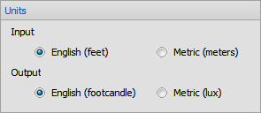
Lighting power density is calculated in terms of Watts per unit area; W/ft² or W/m² depending on system settings. See Settings Luminaires for information on changing the units used in Visual.
Calculations are based on the values in the Luminaire Schedule. Values input to the Luminaire Schedule should be ballast Watts based on the most common usage of LPD. The value imported to the Luminaire Schedule from the IES file may be the value measured during testing, lamp Watts, or ballast Watts. Care should be taken to include the correct value based on published manufacturer data for the specific lamp and ballast components used.
